

Choosing a Gear Drive Motor is not simply a matter of matching horsepower to a machine. The decision affects energy use, noise, maintenance, product quality, and operating life. The International Energy Agency reports that electric motor systems consume about 53% of global electricity. This figure explains why motor selection deserves engineering attention, even for a small packaging line. A motor that turns a conveyor smoothly may still waste energy through poor gearing, incorrect sizing, or unnecessary speed control.
Practical selection begins with the application. Measure the required torque, output speed, duty cycle, starting load, ambient temperature, and mounting position. A conveyor carrying sealed cartons may need high starting torque and frequent stops. A mixer handling thick material may require continuous overload capacity. The U.S. Department of Energy recommends evaluating complete motor-driven systems rather than motors alone. That approach includes the gearbox, coupling, controls, and driven equipment.
Standards also provide useful boundaries. IEC 60034-30-1 classifies motor efficiency levels, while IEC 60034-1 addresses general motor performance requirements. However, efficiency labels cannot replace field judgment. A higher-efficiency motor may perform poorly if the gearbox ratio is wrong. It may also create avoidable costs when servicing access is limited. A spreadsheet helps. It does not see dust, vibration, misalignment, or an operator’s daily routine. This guide examines torque calculations, gear ratios, efficiency, protection ratings, thermal conditions, and lifecycle costs. Some applications remain imperfectly specified, so conservative assumptions and on-site validation are essential.
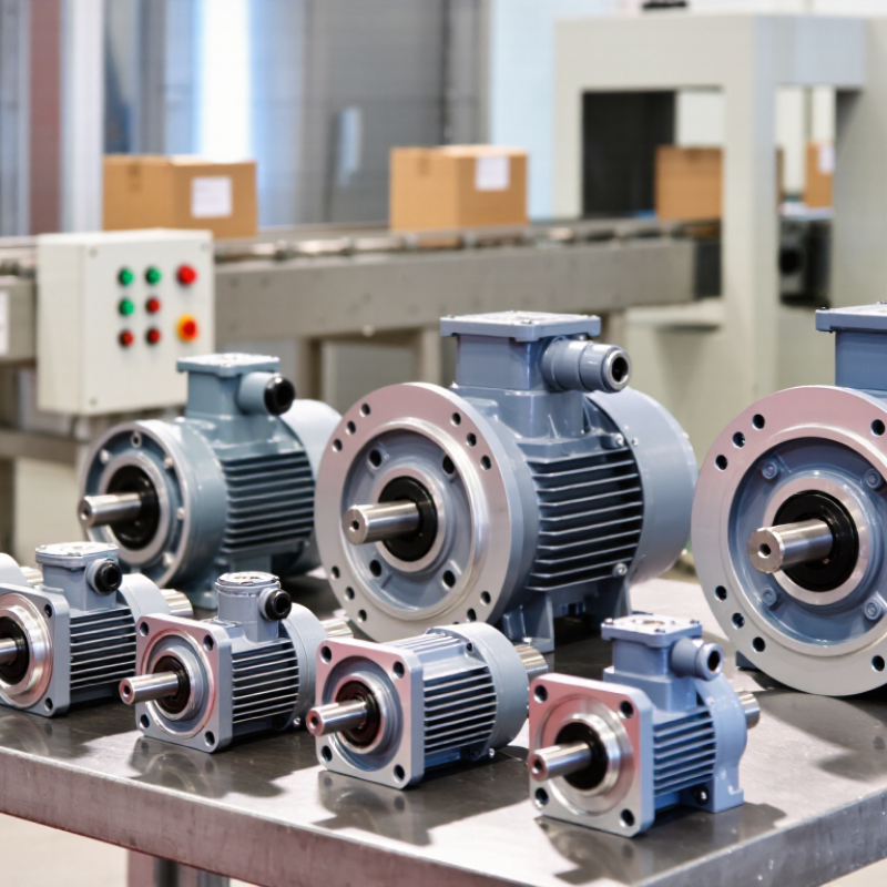
How to Choose a Gear Drive Motor for Your Application?
Define the Application Requirements and Operating Conditions
Start with the load. Measure the required torque, speed, and running time before selecting a gear drive motor. A conveyor carrying 80 kilograms may need different torque during startup than during steady movement. Record the starting load, peak load, and expected load changes. Do not rely only on the average value.
In practical design reviews, I check the output shaft speed, gearbox ratio, mounting space, and shaft direction together. A motor running continuously for eight hours needs different thermal protection than one operating for ten seconds per cycle. Reversing motion also increases mechanical stress. Include acceleration time, braking frequency, and allowable noise in the requirements. Small details often control the final choice.
Conditions change. Check the surrounding temperature, humidity, dust, vibration, and possible water exposure. A motor installed beside a hot machine may lose cooling capacity. A dusty workshop can also shorten the life of seals and bearings. Confirm the available voltage, frequency, control method, and protection rating. Leave a sensible torque margin, but avoid excessive oversizing, which can increase cost and reduce efficiency. One common mistake is choosing from rated power alone. A better assessment compares the real duty cycle with the motor’s thermal and mechanical limits. Test the selected unit under the heaviest realistic condition, then review the result before final installation.
Define the application requirements and operating conditions before selecting a gear drive motor. The chart shows representative continuous and peak torque requirements for common industrial applications.
Select a motor and gearbox with sufficient continuous torque for normal operation and adequate peak torque for startup, acceleration, and temporary overloads. Also verify output speed, duty cycle, load inertia, ambient temperature, mounting position, and available service factor.
Choosing the correct gearbox type starts with the machine’s real operating conditions. A helical gearbox suits steady conveyor motion and usually runs efficiently. A planetary gearbox fits compact systems requiring high torque in limited space. Worm gearboxes offer large reduction in a small package, but their heat and efficiency losses need careful checking.
Calculate the reduction ratio from motor speed to required output speed. For example, a 1,800 rpm motor producing 60 rpm needs approximately a 30:1 ratio. Do not select the ratio from speed alone. Check starting torque, shock loads, duty cycle, and the time spent near peak load. A conveyor carrying wet material may need more torque than its average calculation suggests.
Measure the available space.
I also check backlash, lubrication access, mounting direction, and shaft loading before approving a gearbox. These details often cause field problems. A ratio that looks efficient on paper may perform poorly during frequent starts. In my experience, selecting the smallest possible gearbox is a weak decision when load changes are unpredictable. Allow a practical service factor, but avoid excessive oversizing, which can increase cost and reduce system responsiveness. Confirm the manufacturer’s torque ratings under your actual duty conditions, not only catalog values. The final choice should balance speed, torque, efficiency, thermal capacity, and maintenance access.
| Gearbox Type | Typical Reduction Ratio | Typical Efficiency | Backlash Range | Torque Density | Best-Suited Applications | Main Advantages | Common Limitations |
|---|---|---|---|---|---|---|---|
| Spur Gearbox | 3:1 to 10:1 per stage; higher ratios require multiple stages | Approximately 90%–97% per stage | Approximately 10–30 arcmin, depending on design and wear | Low to medium | Small conveyors, compact actuators, mixers, office equipment, and low-cost automation | Simple construction, compact size, economical production, and good availability | Higher noise at elevated speed; limited ability to handle shock loads and very high torque |
| Helical Gearbox | 3:1 to 10:1 per stage; approximately 5:1 to 100:1 in common multi-stage units | Approximately 90%–97% overall, depending on the number of stages | Approximately 10–30 arcmin in standard configurations | Medium to high | Industrial conveyors, pumps, packaging machinery, material handling, and continuous-duty equipment | Quiet operation, smooth tooth engagement, high load capacity, and good continuous-duty performance | Produces axial thrust; usually requires thrust-bearing support and accurate alignment |
| Planetary Gearbox | 3:1 to 10:1 per stage; approximately 3:1 to 100:1 in multi-stage configurations | Approximately 90%–98% overall | Approximately 3–15 arcmin; precision versions can be lower | High | Robotics, servo systems, indexing tables, machine tools, mobile equipment, and high-performance automation | High torque-to-size ratio, balanced load sharing, low inertia, and good repeatability | Higher cost and greater sensitivity to lubrication, assembly accuracy, and overloads |
| Worm Gearbox | 5:1 to 100:1 in a single stage; higher ratios are possible in selected designs | Approximately 40%–90%; efficiency generally decreases as the ratio increases | Approximately 10–60 arcmin in standard units | Medium | Lifts, gates, indexing mechanisms, conveyors, packaging machines, and right-angle drives | High ratio in one stage, compact right-angle layout, quiet operation, and possible self-locking behavior | Lower efficiency, greater heat generation, and self-locking cannot be assumed without verification |
| Bevel Gearbox | 1:1 to 5:1 per stage; higher ratios normally use additional stages | Approximately 90%–96% overall | Approximately 10–30 arcmin in standard configurations | Medium to high | Right-angle conveyors, machine tools, mixers, packaging lines, and systems requiring efficient direction changes | Efficient 90-degree power transmission, good load capacity, and flexible shaft arrangements | More expensive and alignment-sensitive than basic spur or worm gearboxes |
| Cycloidal Gearbox | Approximately 6:1 to 119:1; multi-stage designs provide higher ratios | Approximately 80%–95% overall | Typically less than 1–3 arcmin in precision designs | High | Robotic joints, positioning systems, indexing equipment, heavy-duty actuators, and shock-load applications | High shock-load capacity, low backlash, compact size, and long service life when correctly lubricated | More complex design, higher cost, and possible vibration or noise at high speed |
| Selection Dimension | How to Determine It | Typical Design Guidance | Why It Matters |
|---|---|---|---|
| Required Output Speed | Define the required speed at the gearbox output shaft in revolutions per minute (rpm). | Use the actual operating speed rather than the maximum possible speed. | The output speed determines the required reduction ratio and affects motor frequency, heat, and service life. |
| Reduction Ratio | Reduction ratio = Motor speed ÷ Required output speed | Example: 1,500 rpm motor ÷ 60 rpm output speed = 25:1 nominal ratio. | A correctly selected ratio prevents excessive motor speed, insufficient torque, or unnecessary gearbox stages. |
| Output Torque | Torque (N·m) = 9,550 × Power (kW) ÷ Speed (rpm) | Calculate torque at the gearbox output and include the gearbox efficiency. | The gearbox must meet both the continuous torque and the peak or acceleration torque. |
| Service Factor | Multiply the calculated application torque by a factor based on load variation, starts per hour, and operating time. | Common preliminary values: 1.0–1.25 for smooth light duty, 1.25–1.75 for moderate duty, and 1.75–2.5 or more for severe shock loading. | It provides a practical margin for variable loads, starts, stops, impact, and uncertain operating conditions. |
| Continuous and Peak Torque | Compare both the running torque and the highest transient torque with the gearbox ratings. | Peak torque can occur during startup, emergency stops, jams, rapid acceleration, or direction changes. | A gearbox may survive the continuous load but fail if repeated peak torque exceeds its allowable rating. |
| Motor Power | Motor power should cover output power ÷ gearbox efficiency, with allowance for acceleration and losses. | Select the motor from the required torque-speed curve, not from power alone. | Two motors with the same power can provide different torque, acceleration, and thermal performance. |
| Duty Cycle | Record operating hours per day, starts and stops per hour, load percentage, and reversing frequency. | Continuous duty and frequent cycling normally require more thermal capacity than intermittent operation. | Duty cycle affects temperature rise, bearing life, tooth fatigue, lubricant life, and permissible torque. |
| Backlash Requirement | Specify the maximum permitted angular clearance at the output shaft. | Use precision planetary or cycloidal designs for positioning; standard worm or spur units may be suitable for non-precision motion. | Backlash influences positioning accuracy, repeatability, vibration, and reversal performance. |
| Mounting and Shaft Arrangement | Define inline or right-angle orientation, mounting position, shaft direction, flange dimensions, and allowable overhung load. | Confirm whether the gearbox uses foot, flange, face, or shaft mounting and verify the lubrication position. | Incorrect mounting or excessive radial and axial loads can cause premature bearing and seal failure. |
| Environmental Conditions | Check ambient temperature, dust, moisture, washdown exposure, altitude, and hazardous-area requirements. | Use suitable sealing, corrosion protection, lubricant viscosity, and enclosure protection for the environment. | Environmental conditions directly affect cooling, corrosion resistance, insulation life, and lubricant performance. |
Selecting a gear drive motor starts with the load, not the catalog. Measure the required torque at the output shaft, including friction, incline, acceleration, and payload variation. For a drum with a 0.08-meter radius and a 120-newton load, static torque is 9.6 newton-meters. Add a suitable starting margin; ignoring acceleration is a common field mistake.
Speed comes next. If the machine must rotate at 30 revolutions per minute, choose the gear ratio from the motor’s rated speed and expected slip. Motor power follows the relationship P = T × ω. At 9.6 newton-meters and 30 revolutions per minute, the mechanical output is about 30 watts before losses. Include gearbox and electrical efficiency, then check continuous and peak duty separately. The U.S. Department of Energy’s Motor Systems Market Assessment reports that motor-driven equipment can represent about 70% of industrial electricity consumption, so small efficiency errors can become expensive.
Use the duty cycle to refine the selection. A conveyor moving every few minutes may need high starting torque, while a fan usually needs steadier operation. Review thermal limits, allowable overload, brake requirements, shaft loading, and ambient temperature. The International Energy Agency has reported that electric motor systems consume roughly half of global electricity, making correct sizing important beyond performance alone. A spreadsheet helps, but it can still hide poor assumptions. Measure the real load when possible. Field data is often less convenient, yet more trustworthy.
A gear drive motor should fit the machine before it fits the budget. Check shaft alignment, mounting space, load direction, and access for tools. Foot-mounted units suit frames with flat, rigid bases. Flange-mounted units save space, but they demand accurate face alignment. A hollow-shaft design can reduce couplings and parts. Fit matters. I once saw a compact motor selected too quickly. Its housing blocked a nearby inspection cover, turning a simple service task into a shutdown.
Controls should match the motor’s operating pattern. A basic starter may suit constant-speed conveying, while variable-speed control helps with changing loads. Confirm voltage, current, braking needs, and enclosure protection before ordering. Keep acceleration limits conservative when the gearbox drives a heavy drum. Fast starts can create shock loads. Measure actual running current during commissioning, rather than trusting only catalog estimates. That field check often reveals an oversized or poorly loaded motor.
Maintenance access influences total cost more than many buyers expect. Look for accessible lubrication points, replaceable seals, and clear inspection procedures. Record temperature, noise, vibration, and current readings during normal operation. Keep records. A low purchase price can become expensive when technicians need special tools or frequent removal. Compare energy use, spare parts, labor hours, downtime, and expected service life. The calculation may still be imperfect because production losses are difficult to predict. Review it with maintenance staff, not just purchasing. Their daily experience can expose costs hidden in a neat spreadsheet.

